
Page 5 - Open-Access-Nov-2019
P. 5
TECHNICAL PAPER
1.2 Dampers • Grade of concrete used M 40
1.2.1 Fluid viscous dampers • Column size 750 mm X 750 mm
Fluid viscous dampers are most commonly used as a passive • Beam size 230 mm X 450 mm
energy dissipation device. It consists of a hollow cylinder filled • Shear wall thickness 200 mm
with a viscous liquid, silicone is mostly the type of fluid used • Thickness of outrigger wall 500 mm
in these kinds of dampers. The damper piston rod pushes the
piston head making the fluid to flow through the orifices either • Slab thickness 230 mm
around or through the piston head. The fluid flows at high • Live load 3kN/m 2
velocities which results in the development of friction between
fluid particles and the piston head. The friction forces developed • Height of each story 3.5 m
will result in energy dissipation in the form of heat. • Total height of the structure 210 m
2. OBJeCtIves OF PReseNt wORK
This research work is focused on analyzing the performance of
the outrigger structural system with dampers. The objectives of
the present study are as follows.
• To study the performance of a structure with one and two
outriggers located at their optimum location with dampers.
• To study the performance by varying the flexural rigidity
ratio viz:(flexural rigidity of core wall with respect to the
flexural rigidity of the outrigger) with dampers.
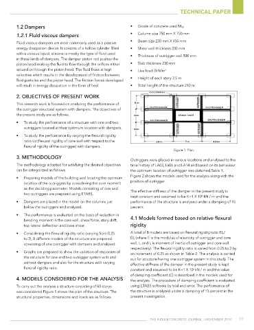
Figure 1: Plan.
3. MetHODOLOGY
Outriggers were placed in various locations and analysed to the
The methodology adopted for satisfying the desired objectives time history of LA03, La06 and LA14 and based on its behaviour
can be categorized as follows the optimum location of outrigger was obtained,Table 1,
• Preparing models of the building and locating the optimum Figure 2 shows the models used for the analysis along with the
location of the outriggers by considering the core moment position of outrigger.
as the deciding parameter. Models consisting of one and The effective stiffness of the damper in the present study is
two outriggers are prepared using ETABS.
kept constant and assumed to be K=1 X 10 kN / m and the
6
• Dampers are placed in the model on the columns just performance of the structure is analysed under a damping of 15
below the outriggers and analysed. percent.
• The performance is evaluated on the basis of reduction in
bending moment in the core wall, shear force, story drift, 4.1 Models formed based on relative flexural
top lateral deflection and base shear. rigidity
• Considering the flexural rigidity ratio (varying from 0.25 A total of 8 models are based on flexural rigidity ratio EI o/
to 2), 8 different models of the structure are prepared EI s (where E is the modulus of elasticity of outrigger and core
consisting of one outrigger with dampers and analysed. wall, I o and I s is moment of inertia of outrigger and core wall
respectively). The flexural rigidity ratio is varied from 0.25 to 2 by
• Graphs are prepared to show the variation of responses of an increment of 0.25 as shown in Table-2. The analysis is carried
the structure for one and two outrigger system with and out for structure having one outrigger system in this study. The
without dampers and also for the structure with varying effective stiffness of the damper in the present study is kept
flexural rigidity ratio. constant and assumed to be K=1 X 10 kN / m and the value
6
of damping coefficient (C) is described in the models used for
4. MODeLs CONsIDeReD FOR tHe ANALYsIs the analysis. The procedure of damping coefficient is evaluated
To carry out the analysis a structure consisting of 60 storys using ETABS software by trial and error. The performance of
was considered Figure 1 shows the plan of the structure. The the structure is analyzed under a damping of 15 percent in the
structural properties, dimensions and loads are as follows. present investigation.
The IndIan ConCreTe Journal | november 2019 17