
Page 5 - Open-Access-Mar-2020
P. 5
TECHNICAL PAPER
%QPETGVG s /
4GKPHQTEGOGPV s (G
.. M0 O 5+&. M0 O
%QXGT VQ DGCO CPF UNCD OO
; " E E
; " E E ; " E E
/CUQPT[ RKNNCT
OO
; " E E
; " E E
OO OO
& U
D 5GEVKQP # # %QPXGPVKQPCN FGUKIP
$ # ; " E E
; " E E
; " E E
OO
; " E E
; " E E
OO
E 5GEVKQP # # 2TQRQUGF FGUKIP
C 2NCP
#NN FKOGPUKQPU CTG KP OO
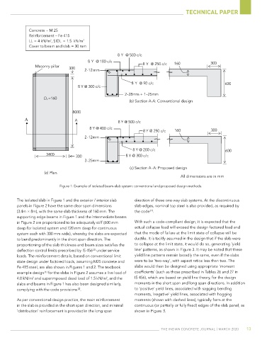
Figure 1: Example of isolated beam-slab system: conventional and proposed design methods.
The isolated slab in Figure 1 and the exterior / interior slab direction of these one-way slab systems. At the discontinuous
panels in Figure 2 have the same clear span dimensions slab edges, nominal top steel is also provided, as required by
[2]
(3.4m × 8m), with the same slab thickness of 160 mm. The the code .
supporting edge beams in Figure 1 and the intermediate beams
in Figure 2 are proportioned to be adequately stiff (600 mm With such a code-compliant design, it is expected that the
deep for isolated system and 720 mm deep for continuous actual collapse load will exceed the design factored load and
system each with 300 mm wide), whereby the slabs are expected that the mode of failure at the limit state of collapse will be
to bend predominantly in the short span direction. The ductile. It is tacitly assumed in the design that if the slab were
proportioning of the slab thickness and beam sizes satisfies the to collapse at the limit state, it would do so, generating ‘yield
[2]
deflection control limits prescribed by IS 456 under service line’ patterns, as shown in Figure 3. It may be noted that these
loads. The reinforcement details, based on conventional limit yield line patterns remain broadly the same, even if the slabs
state design under factored loads, assuming M25 concrete and were to be ‘two-way’, with aspect ratios less than two. The
Fe 415 steel, are also shown in Figures 1 and 2. The textbook slabs would then be designed using appropriate ‘moment
example design for the slabs in Figure 2 assumes a live load of coefficients’ (such as those prescribed in Tables 26 and 27 in
[1]
2
2
4.0 kN/m and superimposed dead load of 1.5 kN/m , and the IS 456), which are based on yield line theory, for the design
slabs and beams in Figure 1 has also been designed similarly, moments in the short span and long span directions. In addition
complying with the code provisions . to ‘positive’ yield lines, associated with sagging bending
[2]
moments, ‘negative’ yield lines, associated with hogging
As per conventional design practice, the main reinforcement moments (shown with dashed lines), typically form at the
in the slab is provided in the short span direction, and minimal continuous (or partially or fully fixed) edges of the slab panel, as
‘distribution’ reinforcement is provided in the long span shown in Figure 3.
The IndIan ConCreTe Journal | MarCh 2020 13