
Page 4 - Open Access - November
P. 4
TECHNICAL PAPER
BRBs are designed in such a way that only central core segments fundamental period of the strengthened frame as compared to
are expected to undergo inelastic deformation, whereas the original unstrengthened frame. Hence, it is reasonable to
both transition and end segments of BRBs are designed to assume the same design base shear for the strengthened frame
remain elastic. The cross-section area of the transition and as that of the unstrengthened frame.
end segments of BRB is taken as 1.6 and 2.2 times the area of
BRB core segment, respectively. The total length of transition
segments, elastic end zones, and core segment may be taken
[21]
as 6, 24, and 70% of the distance between the work points .
The ultimate axial strengths of BRBs in tension and compression
can be computed as the strain-hardening adjustment factor (ω)
times the corresponding yield strengths. The values of β and ω
for BRBs are considered as 1.10 and 1.40, respectively .
[22]
3.2 computation of design Base Shear of
Strengthened Frame
The dynamic behaviour OGS frame is very often considered
as similar to that of a single degree-of-freedom system as the (a)
lateral displacement demand is mostly concentrated at the soft
ground story level with all upper stories having masonry infill
walls behaving like a rigid body. The installation of BRBs in the
soft-story would contribute to the story stiffness. For a single-
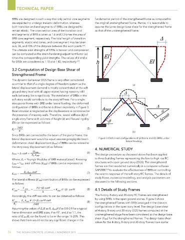
story portal frame with BRB under lateral loading, the deformed
configuration of BRBs and frame is shown separately in Figure 3.
Beam rotation is neglected as the displacement is constrained in
the presence of masonry walls. Therefore, lateral stiffness (K f) of
single-story frame with columns of height (h) and flexural rigidity
(EI) can be expressed as follows:
24EI
K f = (5)
h 3 (b)
Since BRBs are connected to the beam of the portal frame, the
lateral displacement would be equal assuming negligible beam Figure 3: Deformed configurations of (a) frame and (b) BRBs under
deformation. Axial displacement (∆ BRB) of BRBs can be related to lateral loading.
the story sway displacement (∆) as follows:
4. nuMErIcAl Study
∆ BRB = ∆ cosθ = TL BRB (6) The design procedure as discussed above has been applied
E S A BRB
Where, E s = Young’s Modulus of BRB material (steel). Knowing to three building frames representing the low-to-high rise RC
L BRB = ⁄ sinθ, axial stiffness (K BRB) of BRBs can be expressed as structures with open ground story (OGS). The strengthened
h
follows : frames are then modelled numerically in a computer software
SAP2000 to evaluate the effectiveness of BRBs in controlling
[23]
E S A BRB sinθ
K BRB = (7) the seismic response of the soft-story RC frames. The details of
h
study frame, numerical modelling, and analysis parameters are
The lateral stiffness (K' BRB) contribution of BRBs can be expressed
as follows: discussed in the following sections.
V T(1+β) cosθ
K' = BRB = = K (1+β) cos θ (8) 4.1 details of Study Frames
2
BRB ∆ ∆ BRB
Accordingly, the stiffness ratio to can be obtained as follows: The 4-story, 8-story and 20-story RC frames are strengthened
K' BRB = E A BRB h (1+β) cos θ sinθ (8) by using BRBs in the open ground stories. Figure 4 shows
2
2
S
K 24EI the strengthened frames with BRBs arranged in the chevron
f
configurations in the open story level. The design base shear
Assuming the values of E s/E as 8, A BRBh /I as 0.8-0.9 for a typical of 4-story, 8-story and 20-story OGS frames computed at the
2
frame dimension and BRB sizes, θ as 45°, and β as 1.1, the unstrengthened stage have been considered as the design base
ratio of K' BRB/K f can be found to be in the range 15-20%. This
shows that there would not be any significant change in the shear (V BRB) for the strengthened frames. The design base shear
values for the 4-story, 8-story and 20-story frames have earlier
26 The IndIan ConCreTe Journal | november 2019