
Page 6 - Open Access - November
P. 6
TECHNICAL PAPER
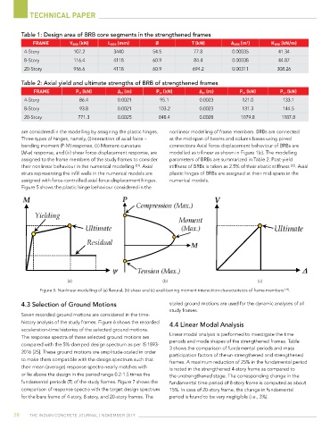
table 1: design area of BrB core segments in the strengthened frames
frame V BrB (kn) l BrB (mm) Ø t (kn) a BrB (m ) k BrB (kn/m)
2
4-Story 107.2 3440 54.5 77.8 0.00035 41.34
8-Story 116.4 4118 60.9 84.4 0.00038 44.87
20-Story 956.6 4118 60.9 694.2 0.00311 308.26
table 2: Axial yield and ultimate strengths of BrB of strengthened frames
frame P yt (kn) ∆ yt (m) P yc (kn) ∆ yc (m) P ut (kn) P uc (kn)
4-Story 86.4 0.0021 95.1 0.0023 121.0 133.1
8-Story 93.8 0.0021 103.2 0.0023 131.3 144.5
20-Story 771.3 0.0025 848.4 0.0028 1079.8 1187.8
are considered in the modelling by assigning the plastic hinges. nonlinear modelling of frame members. BRBs are connected
Three types of hinges, namely, (i)interaction of axial force – at the mid-span of beams and column bases using pined
bending moment (P-M) response, (ii) Moment-curvature connections Axial force-displacement behaviour of BRBs are
(M-ψ) response, and (iii) shear force-displacement response, are modelled as trilinear as shown in Figure 1(c). The modelling
assigned to the frame members of the study frames to consider parameters of BRBs are summarized in Table 2. Post-yield
[22]
[24]
their nonlinear behaviour in the numerical modelling . Axial stiffness of BRBs is taken as 2.5% of their elastic stiffness . Axial
struts representing the infill walls in the numerical models are plastic hinges of BRBs are assigned at their mid-spans in the
assigned with force-controlled axial force-displacement hinges. numerical models.
Figure 5 shows the plastic hinge behaviour considered in the
(a) (b) (c)
[19]
Figure 5: Nonlinear modelling of (a) flexural, (b) shear and (c) axail-bening moment interactiion characteristcis of frame members .
4.3 Selection of Ground Motions scaled ground motions are used for the dynamic analyses of all
study frames.
Seven recorded ground motions are considered in the time-
history analysis of the study frames. Figure 6 shows the recorded 4.4 linear Modal Analysis
acceleration-time histories of the selected ground motions.
Linear modal analysis is performed to investigate the time
The response spectra of these selected ground motions are
periods and mode shapes of the strengthened frames. Table
compared with the 5%-damped design spectrum as per IS:1893- 3 shows the comparison of fundamental periods and mass
2016 [25]. These ground motions are amplitude-scaled in order participation factors of the un-strengthened and strengthened
to make them compatible with the design spectrum such that
frames. A maximum reduction of 25% in the fundamental period
their mean (average) response spectra nearly matches with is noted in the strengthened 4-story frame as compared to
or lie above the design in the period range 0.2-1.5 times the the unstrengthened stage. The corresponding change in the
fundamental periods (T) of the study frames. Figure 7 shows the fundamental time period of 8-story frame is computed as about
comparison of response spectra with the target design spectrum 15%. In case of 20-story frame, the change in fundamental
for the bare frame of 4-story, 8-story, and 20-story frames. The period is found to be very negligible (i.e., 3%).
28 The IndIan ConCreTe Journal | november 2019