Page 40 - ICJ Jan 2023
P. 40

TECHNICAL PAPER                                            COLLECTOR’S EDITION


                              EXPERIMENTAL INVESTIGATION

                              The primary aim of this investigation was to provide
                              answers to the following questions:

                                  (i)  How  do  the  web  openings  affect  the
                                      strength of prestressed concrete beams?


                                  (ii)  How does the serviceability characteristics
                                      e.g., cracking, deflection etc., get affected
                                      as a consequence of these openings?

                              Experiments  were  conducted  on  9  prestressed
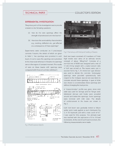
                                                                            Fig 3 Test set-up with third-point loading of beams
                              concrete  T-beams,  the  details  of which  are  given
                              in  Table  1.  Two  openings  were  provided  in  each   Each test beam consisted of 5 numbers of 7-mm
                              beam; in some cases the openings were provided   high tensile  steel  wires  of  an  ultimate  tensile
                                                                                                       2
                              in the shear span whereas in 3 beams the openings   strength  of  about  180kg/mm .  Concrete  of a
                                                                            nominal mix of M350 was designed and a mix of
                              were in the region of constant moment. The results
                                                                            1:1.42:2.74  by  weight  with  a  water-cement  ratio
                              of  tests  on  these  beams with  openings were
                                                                            of  0.41  was  arrived  at.  The  beams  were  cast  in
                              compared with those of a similar solid beam.  wooden forms Fig. 1. An immersion type vibrator
                                                                            was  used  to  vibrate  the  concrete.  Rectangular
                                                                            openings were provided symmetrically  with
                                                                            respect to the midspan. Special care was taken to
                                                                            concrete around these openings. A span of 4.2m
                                                                            was chosen to accommodate these openings and
                                                                            without changing the load points.

                                                                            A  “draped-tendon”  profile  was  given.  6mm  mild
                                                                            steel  was  used  for  stirrups  and  for  flange  steel.
                                                                            Additional  stirrups  and  hooks  were  provided
                                                                            around  and  below  the  openings.  Some  openings
                                                                            were  trimmed  with  mild  steel.  The details
                                                                            of reinforcement in the beam are shown in
                                                                            Fig. 2.

                                                                            Each test  beam was gradually tested to failure
                                                                            under point loads applied at each third-point Fig
                                                                            3.  A  15-t  hydraulic  jack  with  a  least  count  of  0.1-
                                                                            t was used for this purpose. The ultimate  load
                                                                            was  reached  with  the  application  of  8  to  10  load
                                                                            increments. At the end of each load increment, the
                                                                            following measurements were made:
                              Fig 2 Reinforcement details


                                                                        The Indian Concrete Journal | November 2018  41
   35   36   37   38   39   40   41   42   43   44   45