
Page 17 - Open-Access-Sep-2019
P. 17
TECHNICAL PAPER
2.2 Methodology
2.2.1 Printing Procedure
The inkjet 3D printing process is the layer-over-layer printing process which bonds and infuses the powder particles together using
water (binder) as an agent (see Figure 4). This process is easily conducted through the use of 3DP software. The process of the
layering continued until the scaffold was completed. Figure 4 presents a graphical description of the porosity, the infused particles
and binder droplet penetration for the 3DP process.
Figure 4: Schematic of zoomed-in layer description; powder and binder interaction between layers.
2.2.2 Different Curing Regimes
After printing was completed, the 3D printed specimens were
placed in different curing mediums before mechanical strength
testing. Some specimens were cured only in tap water, and
others were cured in the oven at temperatures 40°,60°, 80°, 90°,
100° for 3 hours, then soaked in tap water for 28 days, and then
placed in oven at 40°,60°, 80°, 90°, 100° for 3 hours.
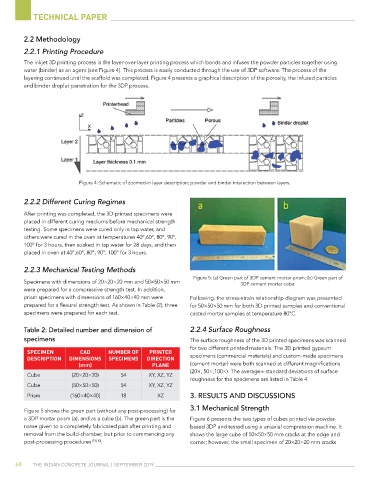
2.2.3 Mechanical Testing Methods
Figure 5: (a) Green part of 3DP cement mortar prism; (b) Green part of
Specimens with dimensions of 20×20×20 mm and 50×50×50 mm 3DP cement mortar cube.
were prepared for a compressive strength test. In addition,
prism specimens with dimensions of 160×40×40 mm were Following, the stress-strain relationship diagram was presented
prepared for a flexural strength test. As shown in Table (2), three for 50×50×50 mm for both 3D printed samples and conventional
specimens were prepared for each test. casted mortar samples at temperature 80°C.
table 2: Detailed number and dimension of 2.2.4 Surface Roughness
specimens The surface roughness of the 3D printed specimens was scanned
for two different printed materials. The 3D printed gypsum
sPEcIMEn cAD nUMbEr of PrIntED
DEscrIPtIon DIMEnsIons sPEcIMEns DIrEctIon specimens (commercial materials) and custom-made specimens
(mm) PlAnE (cement mortar) were both scanned at different magnifications
(20×, 50×,100×). The average± standard deviations of surface
Cube (20×20×20) 54 XY, XZ, YZ
roughness for the specimens are listed in Table 4.
Cube (50×50×50) 54 XY, XZ, YZ
Prism (160×40×40) 18 XZ 3. rESultS anD DiSCuSSionS
Figure 5 shows the green part (without any post-processing) for 3.1 Mechanical Strength
a 3DP mortar prism (a), and as a cube (b). The green part is the Figure 6 presents the two types of cubes printed via powder-
name given to a completely fabricated part after printing and based 3DP and tested using a uniaxial compression machine. It
removal from the build-chamber, but prior to commencing any shows the large cube of 50×50×50 mm cracks at the edge and
post-processing procedures [9] [10] . corner; however, the small specimen of 20×20×20 mm cracks
68 The IndIan ConCreTe Journal | SepTember 2019