
Page 2 - Open-Access-Oct-2020
P. 2
TECHNICAL PAPER
surface of the wrap. Kim et al. conducted an experimental investigation. It is termed in-situ π-anchor and is inspired by the
[14]
study on reinforced concrete T-beams strengthened with work of Mostafa and Razaqpur [15] , who developed, fabricated,
U-wraps, with and without spike anchors. One spike anchor was and tested a π- anchor for preventing debonding of FRP
passed at each end of the U-wrap and inserted into pre-drilled laminates in beams strengthened in flexure. The difference
holes in the concrete. It was found that the anchored U-wrap between the proposed anchor and their anchor is in the stacking
increased the beam strength 40% more than the unanchored of the laminas in the anchor headplate and the placement of the
U-wrap. Although spike anchors have been shown to be laminate between the laminas of the headplate. Furthermore,
effective, they involve penetration through the FRP wrap which their anchor needs to be manufactured and cured prior to
can cause damage to thinner wraps. installation while the proposed anchor can be made in-situ.
Mechanical anchors consist of a steel or FRP plate bonded to
the free ends of the FRP wrap. Steel bolts are then inserted 2. EXPERIMENTAL PROGRAM
through the plate and embedded into pre-drilled holes in
the concrete. Bae and Belarbi conducted an experimental 2.1 Test specimens
[5]
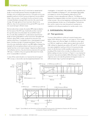
study comparing the behavior of full-scale shear strengthened Fourteen shear-deficient reinforced concrete beams were
T-beams using CFRP U-wraps, anchored by discontinuous tested. With reference to Figure 1, each beam is 170 mm wide,
mechanical anchors. Compared to the un-strengthened control 400 mm deep, with effective depth, d, of 330 mm, shear span,
beam, the shear strength of strengthened beam, fitted with a, of 950 mm, resulting in a shear span-to-depth ratio (a/d) of
discontinuous mechanical anchors, was 48% higher whereas the
strength of the strengthened beam without anchors was 26% 2.88. Inclined or diagonal pre-cracks at 30° and 45° to the beam
higher than the control beam strength. Despite the effectiveness axis were created by inserting a 0.8 mm thick polycarbonate
of mechanical anchors, they also involve penetration through the sheet into the formwork at the specified angle and to avoid
FRP wrap. In addition, they are typically fabricated from steel, bonding of the sheet to the concrete, its surfaces were oiled
which is susceptible to corrosion. before casting concrete. As shown in Figure 1, it was inserted at
the tension face and extended to 80% of the beam height. The
In view of the current situation, to improve the anchorage of objective was to simulate the presence of diagonal cracks in a
FRP U-wraps, a new anchor was developed and tested in this deficient beam requiring shear strengthening.
25 1-10M Stirrups 2-10M Stirrups at 200 mm 5-10M Stirrups at 200 mm
10-M
Stirrups 2-20M Polycarbonate sheet
400
4-20M 30°
50
35
700 mm
30 All Dimensions in mm 100 mm
950 mm
50
170
(a) ()
b
1-10M Stirrups 3-10M Stirrups at 200 mm
5-10M Stirrups at 200 mm
Polycarbonate sheet
45°
500 mm
500 mm
950 mm
(c)
Figure 1: Typical details and dimensions of the test beams (a) cross-section, (b) elevation of beams with 30° pre-crack,
(c) elevation of beams with 45° pre-crack
8 THE INDIAN CONCRETE JOURNAL | OCTOBER 2020