
Page 4 - Open-Access-Oct-2020
P. 4
TECHNICAL PAPER
Anchor Configuration 2 Horizontal Strip
CFRP Anchor
(i) (ii)
(iii) (iii)
(ii) (iv) (i)
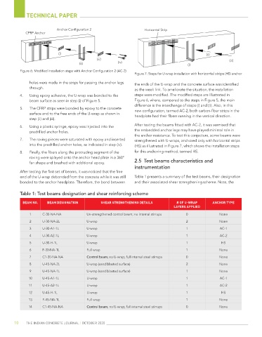
Figure 6: Modified installation steps with Anchor Configuration 2 (AC-2)
Figure 7: Steps for U-wrap installation with horizontal strips (HS) anchor
holes were made in the strips for passing the anchor legs the ends of the U-wrap and the concrete surface was identified
through. as the weak link. To ameliorate the situation, the installation
4. Using epoxy adhesive, the U-wrap was bonded to the steps were modified. The modified steps are illustrated in
beam surface as seen in step (i) of Figure 5. Figure 6, where, compared to the steps in Figure 5, the main
difference is the interchange of steps (i) and (ii). Also, in this
5. The CFRP strips were bonded by epoxy to the concrete new configuration, termed AC-2, both carbon-fiber strips in the
surface and to the free ends of the U-wrap as shown in headplate had their fibers running in the vertical direction.
step (ii) and (iii).
6. Using a plastic syringe, epoxy was injected into the After testing the beams fitted with AC-2, it was surmised that
predrilled anchor holes. the embedded anchor legs may have played minimal role in
the anchor resistance. To test this conjecture, some beams were
7. The roving pieces were saturated with epoxy and inserted strengthened with U-wraps, anchored only with horizontal strips
into the predrilled anchor holes, as indicated in step (iv). (HS) as illustrated in Figure 7, which shows the installation steps
8. Finally, the fibers along the protruding segment of the for this anchoring method, termed HS.
roving were splayed onto the anchor head plate in a 360°
fan shape and brushed with additional epoxy. 2.5 Test beams characteristics and
instrumentation
After testing the first set of beams, it was noticed that the free
end of the U-wrap debonded from the concrete while it was still Table 1 presents a summary of the test beams, their designation
bonded to the anchor headplate. Therefore, the bond between and their associated shear strengthening scheme. Note, the
Table 1: Test beams designation and shear reinforcing scheme
BEAM NO. BEAM DESIGNATION SHEAR STRENGTHENING DETAILS # OF U-WRAP ANCHOR TYPE
LAYERS APPLIED
1 C-30-NA-NA Un-strengthened control beam; no internal stirrups 0 None
2 U-30-NA-2L U-wrap 2 None
3 U-30-A1-1L U-wrap 1 AC-1
4 U-30-A2-1L U-wrap 1 AC-2
5 U-30-H-1L U-wrap 1 HS
6 F-30-NA-1L Full wrap 1 None
7 C1-30-NA-NA Control beam; no U-wrap; full internal steel stirrups 0 None
8 U-45-NA-2L U-wrap (sand blasted surface) 2 None
9 U-45-NA-1L U-wrap (sand blasted surface) 1 None
10 U-45-A1-1L U-wrap 1 AC-1
11 U-45-A2-1L U-wrap 1 AC-2
12 U-45-H-1L U-wrap 1 HS
13 F-45-NA-1L Full wrap 1 None
14 C1-45-NA-NA Control beam; no U-wrap; full internal steel stirrups 0 None
10 THE INDIAN CONCRETE JOURNAL | OCTOBER 2020