
Page 3 - Open-Access-Oct-2020
P. 3
TECHNICAL PAPER
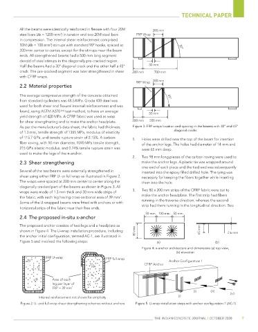
All the beams were identically reinforced in flexure with four 20M 200 mm
2
steel bars (As = 1200 mm ) in tension and two 20M steel bars FRP Wrap
in compression. The internal shear reinforcement comprised
10M (Ab = 100 mm ) stirrups with standard 90° hooks, spaced at 30°
2
200 mm center to center, except for the stirrups near the beam
ends. All strengthened beams had a 500 mm long segment
devoid of steel stirrups in the diagonally pre-cracked region.
Half the beams had a 30° diagonal crack and the other half a 45° 30 mm
crack. The pre-cracked segment was later strengthened in shear 200 mm 700 mm
with CFRP wraps.
200 mm
FRP Wrap
2.2 Material properties
The average compressive strength of the concrete obtained 45°
from standard cyclinders was 48.5 MPa. Grade 400 steel was
used for both shear and flexural internal reinforcement and was
found, using ASTM A370 [16] test method, to have an average
yield strength of 420 MPa. A CFRP fabric was used as wrap 30 mm
for shear strengthening and to make the anchor headplate. 200 mm 500 mm
As per the manufacturer’s data sheet, the fabric had thickness Figure 3: FRP wraps location and spacing in the beams with 30° and 45°
diagonal cracks
of 1.3 mm, tensile strength of 1355 MPa, modulus of elasticity
of 115.7 GPa, and tensile rupture strain of 2.15%. A carbon- 1. Holes were drilled near the top of the beam for insertion
fiber roving, with 10 mm diameter, 1590 MPa tensile strength, of the anchor legs. The holes had diameter of 14 mm and
215 GPa elastic modulus, and 0.74% tensile rupture strain was were 65 mm deep.
used to make the legs of the π-anchor.
2. Two 98 mm long pieces of the carbon roving were used to
2.3 Shear strengthening make the anchor legs. A plastic tie was wrapped around
one end of each piece and the tied end was subsequently
Several of the test beams were externally strengthened in inserted into the epoxy filled drilled hole. The tying was
shear using either FRP U- or full wrap as illustrated in Figure 2. necessary for keeping the fibers together while inserting
The wraps were spaced at 200 mm center to center along the them into the hole.
diagonally cracked part of the beams as shown in Figure 3. All
wraps were made of 1.3 mm thick and 30 mm wide strips of 3. Two 80 x 200 mm strips of the CFRP fabric were cut to
the fabric, with each leg having cross-sectional area of 39 mm . make the anchor headplate. The first strip had fibers
2
Some of the U-wrapped beams were fitted with anchors or with running in the traverse direction, whereas the second
horizontal strips of the fabric near their free ends. strip had them running in the longitudinal direction. Two
50 mm 100 mm 50 mm
2.4 The proposed in-situ π-anchor
The proposed anchor consists of two legs and a headplate as
shown in Figure 4. The U-wrap installation procedure, including 80 mm 65 mm 2.6 mm
the anchor initial configuration, termed AC-1, are illustrated in
Figure 5 and involved the following steps: (a) (b)
Figure 4: π-anchor architecture and dimensions (a) top view,
(b) elevation
FRP U-wrap FRP full wrap
Anchor Configuration 1
CFRP Anchor
Area of each
leg per layer of
FRP = 39 mm 2
(ii) (iii)
(iv)
Internal reinforcement not shown for simplicity (i)
Figure 2: U- and full-wrap shear strengthening schemes without anchors Figure 5: U-wrap installation steps with anchor configuration 1 (AC-1)
THE INDIAN CONCRETE JOURNAL | OCTOBER 2020 9