
Page 5 - Open-Access-Oct-2020
P. 5
TECHNICAL PAPER
numbers 30 and 45 in the designation refer to the diagonal pre-
crack inclination while 1L and 2L denote U-wraps made of one
and two layers of CFRP fabric, respectively.
For convenience, in the ensuing discussion a beam may be
referred to by its number or designation. It should be stated that
the concrete surface in the U-wrapped region of beams, 8 and
Beam 9 was sand blasted for improved bonding; in the other
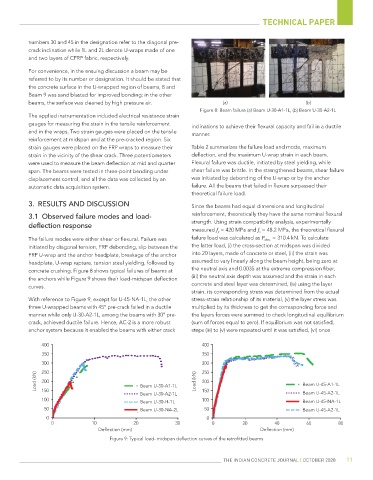
beams, the surface was cleaned by high pressure air. (a) (b)
Figure 8: Beam failure (a) Beam U-30-A1-1L, (b) Beam U-30-A2-1L
The applied instrumentation included electrical resistance strain
gauges for measuring the strain in the tensile reinforcement inclinations to achieve their flexural capacity and fail in a ductile
and in the wraps. Two strain gauges were placed on the tensile manner.
reinforcement at midspan and at the pre-cracked region. Six
strain gauges were placed on the FRP wraps to measure their Table 2 summarizes the failure load and mode, maximum
strain in the vicinity of the shear crack. Three potentiometers deflection, and the maximum U-wrap strain in each beam.
were used to measure the beam deflection at mid and quarter Flexural failure was ductile, initiated by steel yielding, while
span. The beams were tested in three-point bending under shear failure was brittle. In the strengthened beams, shear failure
displacement control, and all the data was collected by an was initiated by debonding of the U-wrap or by the anchor
automatic data acquisition system. failure. All the beams that failed in flexure surpassed their
theoretical failure load.
3. RESULTS AND DISCUSSION Since the beams had equal dimensions and longitudinal
reinforcement, theoretically they have the same nominal flexural
3.1 Observed failure modes and load-
strength. Using strain compatibility analysis, experimentally
deflection response
measured f y = 420 MPa and f c = 48.2 MPa, the theoretical flexural
'
The failure modes were either shear or flexural. Failure was failure load was calculated as P theo. = 310.4 kN. To calculate
initiated by diagonal tension, FRP debonding, slip between the the latter load, (i) the cross-section at midspan was divided
FRP U-wrap and the anchor headplate, breakage of the anchor into 20 layers, made of concrete or steel, (ii) the strain was
headplate, U-wrap rupture, tension steel yielding, followed by assumed to vary linearly along the beam height, being zero at
concrete crushing. Figure 8 shows typical failures of beams at the neutral axis and 0.0035 at the extreme compression fiber,
the anchors while Figure 9 shows their load-midspan deflection (iii) the neutral axis depth was assumed and the strain in each
curves. concrete and steel layer was determined, (iv) using the layer
strain, its corresponding stress was determined from the actual
With reference to Figure 9, except for U-45-NA-1L, the other stress-strain relationship of its material, (v) the layer stress was
three U-wrapped beams with 45° pre-crack failed in a ductile multiplied by its thickness to get the corresponding force and
manner while only U-30-A2-1L, among the beams with 30° pre- the layers forces were summed to check longitudinal equilibrium
crack, achieved ductile failure. Hence, AC-2 is a more robust (sum of forces equal to zero). If equilibrium was not satisfied,
anchor system because it enabled the beams with either crack steps (iii) to (v) were repeated until it was satisfied, (vi) once
400 400
350 350
300 300
N) 250 N) 250
Load (k 200 Beam U-30-A1-1L Load (k 200 Beam U-45-A1-1L
150
Beam U-30-A2-1L 150 Beam U-45-A2-1L
100 100
Beam U-30-H-1L Beam U-45-NA-1L
50 Beam U-30-NA-2L 50 Beam U-45-A2-1L
0 0
0 10 20 30 0 20 40 60 80
Deflection (mm) Deflection (mm)
Figure 9: Typical load- midspan deflection curves of the retrofitted beams
THE INDIAN CONCRETE JOURNAL | OCTOBER 2020 11