
Page 11 - ICJ Feb Openaccess 2026
P. 11
TECHNICAL PAPER
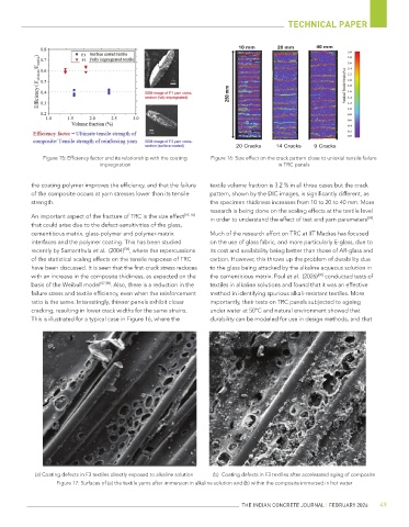
Figure 15: Efficiency factor and its relationship with the coating Figure 16: Size effect on the crack pattern close to uniaxial tensile failure
impregnation in TRC panels
the coating polymer improves the efficiency, and that the failure textile volume fraction is 3.2 % in all three cases but the crack
of the composite occurs at yarn stresses lower than its tensile pattern, shown by the DIC images, is significantly different, as
strength. the specimen thickness increases from 10 to 20 to 40 mm. More
research is being done on the scaling effects at the textile level
An important aspect of the fracture of TRC is the size effect [54, 55] in order to understand the effect of test and yarn parameters .
[59]
that could arise due to the defect-sensitivities of the glass,
cementitious matrix, glass-polymer and polymer-matrix Much of the research effort on TRC at IIT Madras has focused
interfaces and the polymer coating. This has been studied on the use of glass fabric, and more particularly E-glass, due to
recently by Samanthula et al. (2004) , where the repercussions its cost and availability being better than those of AR-glass and
[56]
of the statistical scaling effects on the tensile response of TRC carbon. However, this throws up the problem of durability due
have been discussed. It is seen that the first-crack stress reduces to the glass being attacked by the alkaline aqueous solution in
with an increase in the composite thickness, as expected on the the cementitious matrix. Paul et al. (2026) conducted tests of
[60]
basis of the Weibull model [57,58] . Also, there is a reduction in the textiles in alkaline solutions and found that it was an effective
failure stress and textile efficiency, even when the reinforcement method in identifying spurious alkali-resistant textiles. More
ratio is the same. Interestingly, thinner panels exhibit closer importantly, their tests on TRC panels subjected to ageing
cracking, resulting in lower crack widths for the same strains. under water at 50°C and natural environment showed that
This is illustrated for a typical case in Figure 16, where the durability can be modeled for use in design methods, and that
(a) Coating defects in F3 textiles directly exposed to alkaline solution (b) Coating defects in F3 textiles after accelerated aging of composite
Figure 17: Surfaces of (a) the textile yarns after immersion in alkaline solution and (b) within the composite immersed in hot water
THE INDIAN CONCRETE JOURNAL | FEBRUARY 2026 49