
Page 5 - ICJ Feb Openaccess 2026
P. 5
TECHNICAL PAPER
P 3. FRACTURE OF FIBRE REINFORCED
CONCRETE AS BASIS FOR TOUGHNESS AND
DESIGN
d
a Toughness based on the load-deflection
response of unnotched beams
e Failure in fibre reinforced concrete (FRC), especially in common
2.5 applications with low fibre volume fractions (i.e., less than 1 %),
occur with the development of one or few major cracks, which
3.125
propagate in a stable manner. This justifies the need for fracture
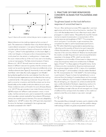
Figure 1: Beams with eccentric notches that give rise to non-planar cracks mechanics based characterization or representation of the
tensile response and toughness of FRC [6,7] . This perspective,
which took years, if not decades, to gain acceptance, has
failure in beams and in cracking originating from corners of
compelled the need for performance-based specifications
walls. The assessment of whether there is any Mode II (sliding or
for FRC rather than following prescriptive approaches (e.g.,
in-plane shear) component in non-planar fracture has been done
considering the simulation of beams with eccentric notches, as indicating just the quantity of fibres to be used irrespective
of their characteristics or the tensile strength or the holistic
in Figure 1, where P is the applied load, d is the beam depth, a response of the concrete). Work at IIT Madras has emphasized
is the notch length, s is the span and e is the eccentricity of the the need to consider the post-crack load-carrying deformation
notch plane from the central or loading plane. In these cases,
capacities in the design of FRC, which has also led to
the crack initiates at the tip of the notch and, due to the loading, investigations on the benefits of fibres based on shape-memory
curves as it propagates. The finite element analysis of García- alloys and amorphous metal, and combinations of different
[2]
Álvarez et al. (2012) showed, based on tests on concrete types of fibres [8-15] on these aspects of the performance. Some
beams of different sizes and two grades, that the cohesive crack of these and other studies led to the prenormative proposal
model can be used to represent the response satisfactorily using for toughness determination of FRC in terms of an equivalent
interface elements (see Figure 2). Importantly, it was concluded flexural strength [16] , which resulted in the first Indian Standard
that Mode I dominates the crack propagation with Mode II for FRC characterization [IS: 17161 (2020) ]. The methodology
[17]
being slightly significant at the crack initiation from the notch. is summarized in Figure 3, where the load-deflection curve is
This has important repercussions as it clarifies that the cracking obtained from the testing of a standard beam and the average
is predominantly in the opening mode even though the crack load over a deflection of 3 mm is used to obtain the equivalent
path is curved or non-planar, and that the analysis can be done flexural strength f e,n as in Equation (1), where l, b and d are the
based solely on the tensile constitutive relation, in such cases. span, width and depth of the beam, respectively, and δ n is the
These conclusions were confirmed in the work of García-Álvarez deflection limit, here 3 mm, for the area under the curve, T e,n .
et al. (2017) through extensive linear elastic fracture mechanics The underlying concept is the use of load averaged over a range
[3]
of deflection that corresponds to the rotation at the crack in an
(LEFM) analysis with different crack extension criteria. In both
element under flexure to obtain an equivalent strength.
works, interface elements were used to represent the crack path,
which provides a simple method for finite element (FE) analysis T e,n l
f e,n = × 2 (1)
without the need for special elements. This was also adopted by δ n bd
Stephen et al. (2018) to obtain the LEFM geometry-dependent The equivalent flexural strength has been used to determine the
[4]
functions for the beam considered in the toughness test crack rotation capacity in conjunction with the yield line design
standard considered in EN 14651 . methodology for slabs-on-grade and pavements in the work
[5]
Figure 2: Meshes in the simulation of non-planar cracking used for notch eccentricities e = 0.25s and e = 0.125s, where s is the span
[from García-Álvarez et al. (2012) ]
[2]
THE INDIAN CONCRETE JOURNAL | FEBRUARY 2026 43