
Page 11 - ICJ Jan 2026
P. 11
TECHNICAL PAPER
3.5 4.5
4
3
Thermal conductivity (W/m.K) 1.5 Thermal conductivity (W/m.K) 2.5 3 2
3.5
2.5
2
1.5
1
0.5
0 0.5 1 0
0 20 40 60 80 100 0 20 40 60 80 100
Porosity (%) Porosity (%)
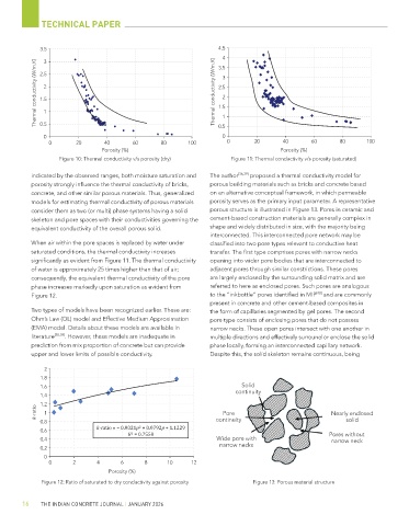
Figure 10: Thermal conductivity v/s porosity (dry) Figure 11: Thermal conductivity v/s porosity (saturated)
indicated by the observed ranges, both moisture saturation and The author [36,39] proposed a thermal conductivity model for
porosity strongly influence the thermal conductivity of bricks, porous building materials such as bricks and concrete based
concrete, and other similar porous materials. Thus, generalized on an alternative conceptual framework, in which permeable
models for estimating thermal conductivity of porous materials porosity serves as the primary input parameter. A representative
consider them as two (or multi) phase systems having a solid porous structure is illustrated in Figure 13. Pores in ceramic and
skeleton and pore spaces with their conductivities governing the cement-based construction materials are generally complex in
equivalent conductivity of the overall porous solid. shape and widely distributed in size, with the majority being
interconnected. This interconnected pore network may be
When air within the pore spaces is replaced by water under classified into two pore types relevant to conductive heat
saturated conditions, the thermal conductivity increases transfer. The first type comprises pores with narrow necks
significantly as evident from Figure 11. The thermal conductivity opening into wider pore bodies that are interconnected to
of water is approximately 25 times higher than that of air; adjacent pores through similar constrictions. These pores
consequently, the equivalent thermal conductivity of the pore are largely enclosed by the surrounding solid matrix and are
phase increases markedly upon saturation as evident from referred to here as enclosed pores. Such pores are analogous
[40]
Figure 12. to the “inkbottle” pores identified in MIP and are commonly
present in concrete and other cement-based composites in
Two types of models have been recognized earlier. These are: the form of capillaries segmented by gel pores. The second
Ohm’s Law (OL) model and Effective Medium Approximation pore type consists of enclosing pores that do not possess
(EMA) model. Details about these models are available in narrow necks. These open pores intersect with one another in
literature [38,39] . However, these models are inadequate in multiple directions and effectively surround or enclose the solid
prediction from mix proportion of concrete but can provide phase locally, forming an interconnected capillary network.
upper and lower limits of possible conductivity. Despite this, the solid skeleton remains continuous, being
2
1.8
1.6 Solid
continuity
1.4
1.2
k-ratio 1 Pore Nearly enclosed
0.8 continuity solid
k-ratio = − 0.0021p + 0.0792p + 1.1229
0.6
R = 0.7558 Pores without
0.4 Wide pore with narrow neck
narrow necks
0.2
0
0 2 4 6 8 10 12
Porosity (%)
Figure 12: Ratio of saturated to dry conductivity against porosity Figure 13: Porous material structure
16 THE INDIAN CONCRETE JOURNAL | JANUARY 2026