
Page 8 - ICJ Feb Openaccess 2026
P. 8
TECHNICAL PAPER
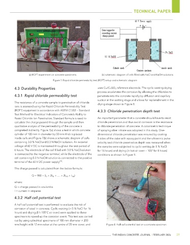
(a) RCPT experiment on concrete specimens (b) schematic diagram of cells filled with NaCl and NaOH solutions
Figure 7: Rapid chloride permeability test (RCPT) setup and schematic diagram
4.3 Durability Properties uses Cu/CuSO 4 reference electrode. The cyclic wetting drying
process accelerates the corrosion by allowing the chlorides to
4.3.1 Rapid chloride permeability test penetrate into the concrete rapidly by diffusion and capillary
suction in the wetting stage and allows for replenishment in the
The resistance of a concrete sample to penetration of chloride drying stage shown in Figure 8.
ions is assessed using the Rapid Chloride Permeability Test
(RCPT) equipment in accordance with ASTM C1202 – Standard 4.3.3 Chloride penetration depth test
Test Method for Electrical Indication of Concrete’s Ability to
Resist Chloride Ion Penetration. Standard formula is used to An important parameter that a concrete should have to resist
calculate the charge passed through the sample and then chloride penetration and thus avoid corrosion is the resistance
qualitative analysis of the permeability of the concrete is to chloride penetration of concrete. A colorimetric technique
completed indirectly. Figure 7(a) shows a test in which concrete of spraying silver nitrate was adopted in this study. One-
cylinder of 100 mm in diameter by 50 mm thick is placed dimensional chloride penetration was ensured by coating
inside cells and Figure 7(b) shows a schematic diagram of cells 5 sides of the cube with epoxy paint and the ultrasonic pulse
containing 3.0 % NaCl and 0.3 N NaOH solution. An external velocity and chloride penetration depth was measured when
voltage of 60 V DC is maintained throughout the test period of the samples were subjected to cyclic wetting (in 5 % NaCl
6 hours. The electrode of the cell filled with 3.0 % NaCl solution for 16 hours) and drying (in hot air oven – 105° for 8 hours)
is connected to the negative terminal, while the electrode of the conditions as shown in Figure 9.
cell containing 0.3 N NaOH solution is connected to the positive
[23]
terminal of the 60 V DC power supply .
The charge passed is calculated from the below formula:
Q = 900 × (I 0 + 2I 30 + .... + 2I 330 + I 360 )
where:
Q = charge passed in coulombs
I = current in amperes
4.3.2 Half-cell potential test
A half-cell potential test is performed to evaluate the risk of
corrosion of steel in concrete. Cyclic wetting (in 5 % NaCl for 16
hours) and drying (8 h 105°C air oven) were applied to these
specimens to speed up the corrosion event. This test was carried
out by using cylindrical specimens of 100 mm diameter × 200
mm height with 12 mm rebar at the centre of 20 mm cover, and Figure 8: Half-cell potential test on a concrete specimen
THE INDIAN CONCRETE JOURNAL | FEBRUARY 2026 29